 | Serveur © IRCAM - CENTRE POMPIDOU 1996-2005.
Tous droits réservés pour tous pays. All rights reserved. |
The Sequencial Drum
Max V. Mathews
Rapport Ircam 27/80, 1980
Copyright © Ircam - Centre Georges-Pompidou 1998
I Introduction
The sequential drum is a device to demonstrate a new
method to play "intelligent instruments" such as a
computer controlled synthesizer. The method
demonstrates a different relationship between the
musician, the score, and the instrument.
As shown in Fig.1, with traditional instruments, all
the information in the score pass trough the musician
who communicates the information to the instrument by
physical gestures. The musician has absolute and fast
control over the sound, but he must be able to read the
score rapidly and make complex gestures quickly and
accurately. Some scores make great demands on his
virtuosity.
A second possible relationship between score, musician
and instrument is shown in Fig. 2. This relationship is
used by pure digital synthesis programs such as MUSIC V
and MUSIC 10. The musician first prepares the score in
a machine readable form. It is then read and performed
by the instrument without further intervention by the
musician. No real time demands are made on the
musician. He can take as much time as he wants to
prepare or revise the score. But he cannot perform the
score in a way that resembles traditional instrumental
performance.
A third relationship is shown in Fig. 3. Here, the
score and the musician both send information directly
to the instrument. The score is a sequence of partial
descriptions of musical events. In general the sequence
is ordered by time. The information not contained in
the score is supplied by the musician in real time
during the performance. In general, the aspects of the
performance which are to be interpreted are supplied by
the musician. The aspects which are not subject to
interpretation are supplied by the score.
In many cases, the timing (tempo, attacks, etc... ) of
the music is one of the most important quantities to be
interpreted. If so, the events in the score can specify
sounds which are concentrated in time or which start at
definite times. The musician can "trigger" the starting
times of these events.
II Sequential drum
Figure 4 is a schematic diagram of the sequential drum.
The drum itself is a rectangular surface which is hit
with the hand or a stick. Hitting the surface does not
produce the music directly. Instead four electrical
signals are sent to the computer-synthesizer. The music
is produced by the synthesizer using these signals
along with a score which is in the computer memory.
The four signals are :
- A trigger pulse occurring when the drum is hit.
- An amplitude signal which is proportional to how
hard the drum is hit.
- and 4. X and Y signals which encode the position of
the stroke.
The signals can be used in any desired way by the
computer-synthesizer. Typically the trigger is used to
start the next event in the score. The amplitude signal
is used to control the loudness of the event. X and Y
signals are used to control the timbre. However many
interesting alternative uses of the signals are
appearant. X and Y might control the physical location
of the sound (assuming the synthesizer has multichannel
outputs). Interesting accent patterns can be performed
by using X or Y to control loudness. If an event is a
group of notes rather than a single note, then one
signal can control the tempo at which the group is
played.
III Monophonic pitch sequences
For much traditional music it is useful to make the
score be the pitches of the sequence of notes to be
played, each event being the pitch of one note. Each
time the performer strikes the drum, he automatically
gets the next pitch in the sequence. Thus the computer
plays the melodic line automatically. The performer
controls all the other parameters - the tempos and
times of occurrence ot the notes, the accents and
dynamics, and the timber.
Why is this mode of control interesting ? Because,
in traditional music, the performer has almost no
freedom in interpreting pitch. If he changes the pitch
from what the composer has written, it is almost always
considered to be a performance error. By contrast, he
has much greater freedom in choosing tempos, making
slight changes in attack times for phrasing, making
accents and choosing loudnesses.
Figure 5 shows a fragment of a monophonic score taken
from a Bach violin sonata. The musical staff and the
corresponding list of pitch events are shown.
The events are written in the 4 C E D language
developed by Curtis Abbott to run on the PDP 11/34 with
the 4C sound synthesizer at IRCAM. This language is
very well adapted to the sequential drum. The rest of
the 4 C E D instructions needed to make the sounds are
shown on Fig. 6
The four signals from the drum are connected to
replace the first four potentiometers on the Cockerell
Box (trigger  Pot 1, amplitude Pot 2, X
Pot 3, Y Pot 4). To adapt to the drum, Abbott
has made a modification to the 4 C E D program so that a trigger
signal (the Z trigger) is generated by Pot 1 increasing
to above a threshold.
Pot 1, amplitude Pot 2, X
Pot 3, Y Pot 4). To adapt to the drum, Abbott
has made a modification to the 4 C E D program so that a trigger
signal (the Z trigger) is generated by Pot 1 increasing
to above a threshold.
Three identical instruments are used to generate the
single voice. Successive notes are rotated amongst the
three instruments so that the "tails" of the decays on
a note can overlap with the beginnings of the next two
notes.
In addition to the trigger signal, the amplitude signal
from the drum is used to control the loudness of the
sound. The X and Y signals are not used.
The performer should have freedom to ornament the
pitch, for example to use vibrato. The drum is probably
not an appropriate control device for vibrato, but
other inputs such as knobs or footpedals can also be
attached to the computer to control these more
continuous quantities.
IV Polyphonic sequences
There is no problem in generalizing the score to encode
a sequence of polyphonic events. Almost any traditional
score with any number of voices can be mapped onto a
single time line which gives the time order of events
in the score. An example of a more complex Bach sonata
is shown in Fig. 7 and 8. In this interpretation the
first ten chords are encoded as single events that are
triggered by a single drum stroke. In the third
measure, the C sharp and sixteenth note G are triggered
together by a single stroke. The C sharp sustains and
the next three sixteenth notes are triggered by the
next three strokes.
V Sequencial piano and multiple input devices
One can easily generalize the concepts of the
sequential drum to multiple drums or to other percusive
devices. Multiple drums might be played by a single
player or by several players.
A sequential piano is an intriguing idea. The piano
would have only ten keys, one for each finger of the
player. Conceptually the task of the computer can be
thought of as moving the right key from the 88 normal
piano keys and placing it under the finger of the
performer at the right instant so that when he
depresses his finger, the right note will be played.
VI Physical piano and multiple input devices
Many ways exist to measure the four signals generated
by the drum. We have chosen a very straightforward
method in which the strength of the stroke is measured
by the size of the signal from contact microphones and
the X and Y position information is measured by
grounding wires from grids of wires which run in the X
and Y directions.
Figure 9 shows a sketch of the mechanical construction
of the drum surface. It consists of six layers :
- The drum head, made of plastic coated fabric.
- A grid of 29 X sensing wires which run perpendicular to the x axis at a spacing of 3/4 inch. Hence the
spacial resolution is 3/4 inch.
- Several x grounding wires parallel to the X axis.
When the drum is hit, one of the X sensing wires
touches an X grounding wire, thus setting an output
voltage level.
- A layer of insulating cloth.
- A grid of 17 Y sensing wires which run perpendicular
to the Y axis at a spacing of 3/4 inch. Hence the Y
resolution is 3/4 inch.
- A 1/4 inch thick aluminium backplate which serves as
mechanical support and as the Y sensor grounding plate.
The contact microphones are attached to the backplate.
Figure 10 shows the resister network attached to the X
and Y sensing wires. The sizes of the resisters are
chosen so that the X and Y sensor output voltages are
linear functions of the X and Y positions of the
stroke.
The right end of the X network is grounded so the
steady state X voltage with no stroke is one unit more
positive than the voltage when the right hand wire is
grounded (approximately 7,5 V).
The lower end of the Y network is ungrounded. Thus if
no Y wire is grounded the Y sensor output is + 15 V.
The large voltage step (15 V to 7,5 V or less) produced
by any drum stroke is used to generate the event
trigger.
VII Description of circuit
The electronics are mounted on two cards underneath the
drum. One of the cards contains a  15 volt power
supply and a + 5 V regulator. The other card contains
the electronics.
15 volt power
supply and a + 5 V regulator. The other card contains
the electronics.
Figure 11 shows a schematic of the electronics.
It operates as follows :
- In the upper chain of electronics, signals from two
contact microphones are processed. The signals are
amplified and summed by amplifiers 1 and 2. The summed
signal is half-wave rectified by dioded DI. The
resulting signal is integrated by R11 and C1. The
voltage on C1 is amplified and sampled at d2 time by
switch S123. The output is held on C7 and buffered by
amplifier 4' to create the AMP output. The value of AMP
goes from 0 to + 5 V.
- The X sensor and Y sensor signals are processed in
similar ways by the circuitry associated with amplifiers
3 and 3'. At d4 time, the voltage on holding capacitors C11 and
C12 is set approximately to 10 V by switches S9 10 11
and S14 15 16.
The 10 volts is greater than the maximum signal which can
be produced by the X or Y sensors.
After d4 time, the holding capacitors C11 and C12 will
discharge and hold at the minimum voltage occurring on
the sensor lines. Thus the holding capacitors will
measure the voltage obtained when one of the sensor wires
is grounded. The X and Y output voltages range from 0 to
5 volts.
- Triggering is done by chain of one shots D 0 through D
4 and associated circuitry. The initial trigger is gotten
from the transition in the Y sensor from + 15 V to some
value less than 7,5 V. The Y sensor voltage is sharpened
by amplifier 5 and formed into an appropriate trigger by
amplifier 4 and associated circuitry. A timing diagram of
the trigger pulses is shown :
- D0 determines the minimum retriggering interval. This
is the minimum interval between successive strokes.
- D1 is trigged on the leading edge of D0 and provides a
time delay during which the microphone signal is
integrated.
- D2 is triggered on the trailing edge of D1 and samples
the amplitude signal.
- D3 is triggered on the trailing edge of D2 and is
amplified to produce the note trigger. The duration of D3
depends on the computer circuit which is to be triggered.
The present Cockerell Box requires a 50 ms trigger for
reliable operation.
- D4 is triggered by the leading edge of D0 and is used
to reset the X and Y signals. D4 must be completed before
the X and Y sensors have ungrounded in order to read
correctly.
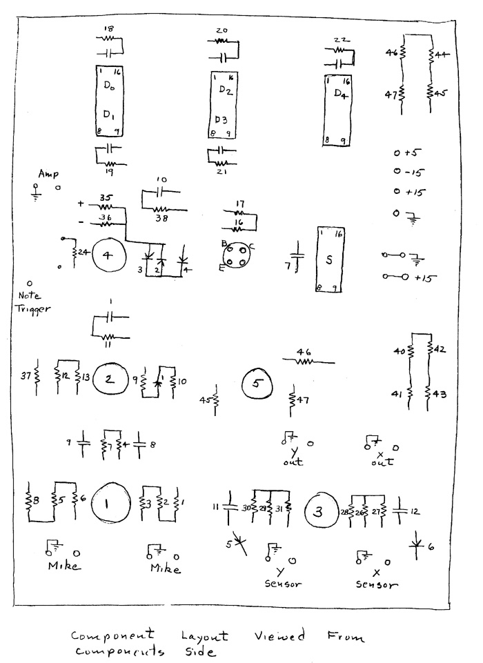
Figure 12 shows the layout of the components.
M.V. Mathews
Figure 1 : Traditional Performance
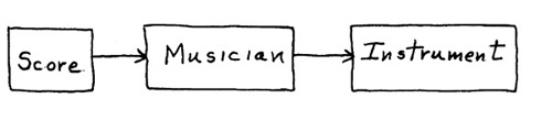
Figure 2 : Pure Digital Synthesis
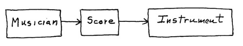
Figure 3 : Real Time Digital Performance
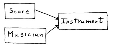
Figure 4 : Sequencial Drum
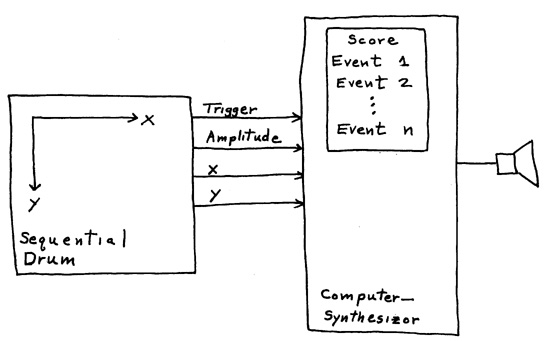
Figure 5 : Monophonic Score (Bach Violin Sonata)
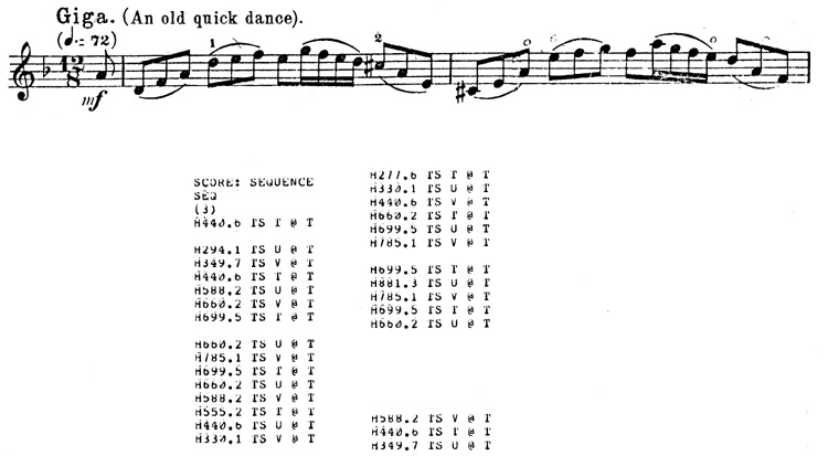
Figure 6 : "4CED" Patch to play Monophonic Score
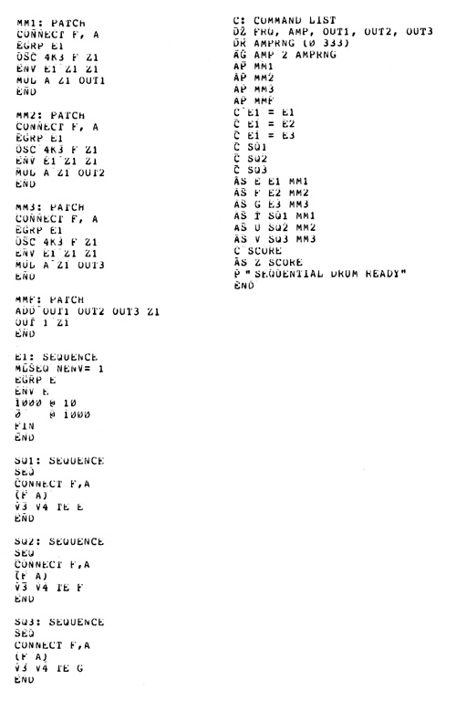
Figure 7 : Polyphonic Score (Bach Violin Sonata)
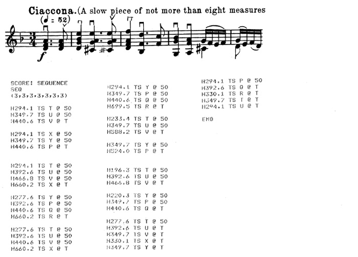
Figure 8 : "4CED" Patch to play Monophonic Score
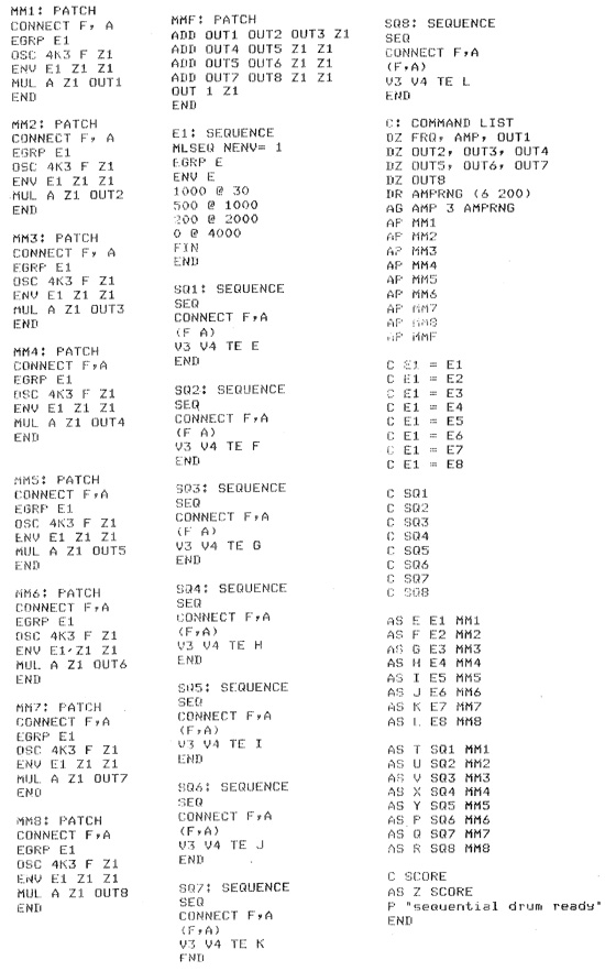
Figure 9 : Sketch showing mechanical construction of drum
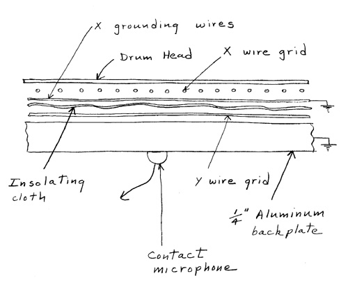
Figure 10 : Resistor network for X and Y sensors (Resistors values in K ohms)
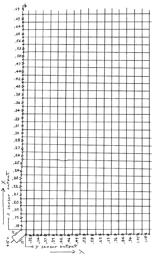
Figure 11 : Schematic of electronics
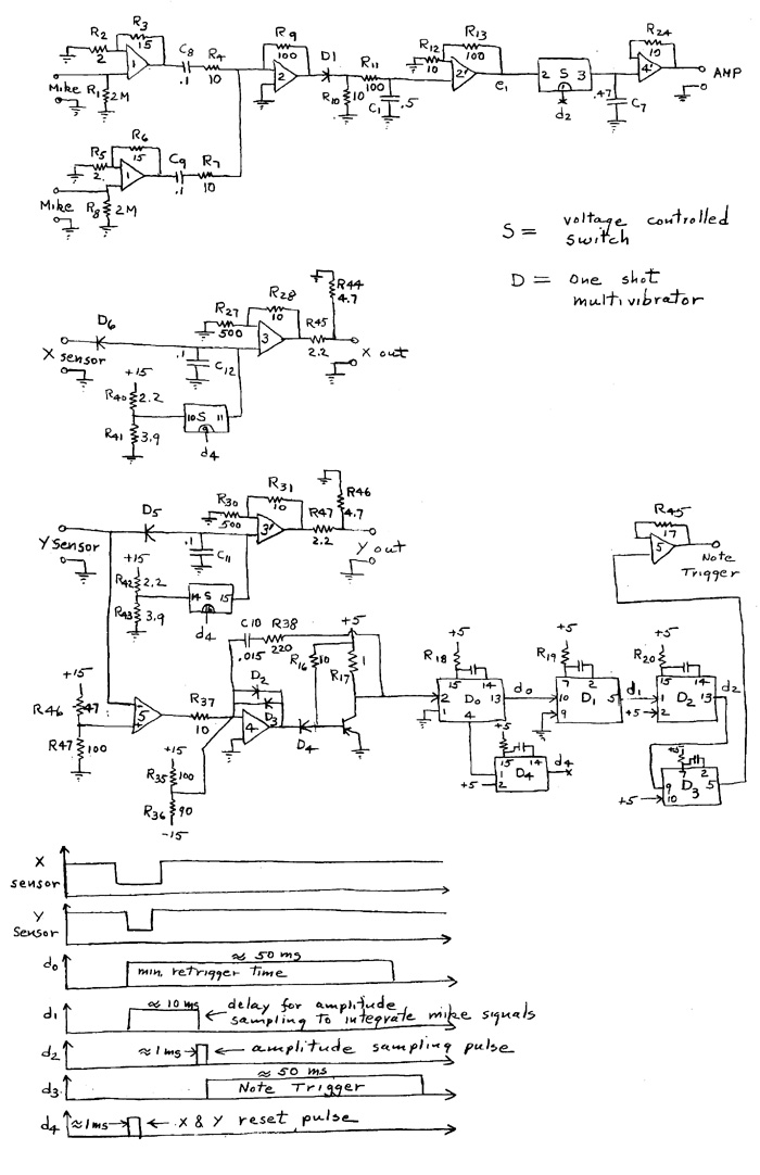
Figure 12 : Component layout
____________________________
Server © IRCAM-CGP, 1996-2008 - file updated on .
____________________________
Serveur © IRCAM-CGP, 1996-2008 - document mis à jour le .