Tous droits réservés pour tous pays. All rights reserved.
| Serveur © IRCAM - CENTRE POMPIDOU 1996-2005. Tous droits réservés pour tous pays. All rights reserved. |
Rapport Ircam 18/78, 1978
Copyright © Ircam - Centre Georges-Pompidou 1978
Abstract
This paper will describe some of the problems encountered in the design and implementation of SYN4B, a programming language for control of the 4B digital synthesizer. These problems are considered from the point of view of a composer, not a computer scientist. It is my hope that other composers working with similarly sophisticated hardware and software may be able to more thoroughly utilize and control their individual computer music environments by gaining some insight into just what sort of decisions and compromises must necessarily be made in the design and implementation of software for a real time computer music system.
While in the course of my description I will outline many of the features of SYN4B, I do not intend for this paper to be
used as a manual for the use of the language, nor as a documentation of the language. Instead, I will focus upon the
problems presented in designing a system which provides a maximum of flexibility and convenience for the composer,
while at the same time allowing access to the synthesizer itself at the lowest level possible. The problems faced in the
development of SYN4B grew out of the conflict between the desire for an ideal system and the necessity of
implementing that system on a particular hardware configuration. The specific points of conflict in any such project
depend necessarily upon the designer's concept of an ideal system and the specific hardware available. The problems
involved in the design of a nonreal time system or a hybrid digital-analog system would, of course, be different from
those described here. However, I believe that users of any system may benefit by seeing the kinds of problems which
are encountered in the design and implementation of a language such as SYN4B. Other composers who find
themselves in a similar position of responsibility for system development may be able to benefit from some of our
solutions to specific problems which we encountered. At the same time, I would hope that any user of any system
might gain some measure of understanding of the causes of the frustrations and annoyances he encounters by
following the progress of the problems encountered in the design and implementation of a computer music system,
and the many compromises necessary in order to reach workable solutions to those problems.
Figure I shows the design of one of the sixty-four oscillators available in the machine. The ramps at the left side and
top of the diagram supply data for the frequency and amplitude of the oscillator, respectively. The ramps are enabled
or disabled by control words, remaining at the current value if disabled, and moving to a specified final value if enabled.
There is also a control word to enable the generation of an interrupt to the system when a ramp arrives at its final
value. The current value in the frequency ramp is processed through the wave table and then given to the x- input of the
multiplier. The value contained in the amplitude ramp is read at the y- input of the multiplier. The output of the mutliplier
is read by an adder, then passed into one of the 15 general purpose registers. The adder may also accept data from
any register to be added to the output of the multiplier. There are also switches at both the x- and y- inputs of the
multiplier by which the user may access data stored in any of the general purpose registers via the OPTION and FM inputs, one of
which may also be used for the FM input to the wavetable, thus permitting frequency modulation.
Any software for the 4B must set the proper control words in the 4B memory to give values to the two ramps, set the
switches for the x- and y- inputs of the multiplier, the input register for the adder, and the output register for each
oscillator. We may begin by considering that instruments are to be defined through the interconnections of oscillators
(setting the switches for the multiplier as well as for the input and output of the adder), and that instruments are defined
by changing the values of the frequency and amplitude ramps.
The switches controlling input to the multiplier, the FM input, and input and output of the adder are all specified by bits
in the control words. The values of the ramps, however, present a slight problem. The ramps are all linear, and they
take as input a final value and an increment (24 bits each), and the current values of the ramps are contained in the
memory in such a way that the ramp may be forced to a given value by putting that value into the "current ramp value"
word. The difficulty is two-fold. First, the user will in many cases want to put a series of ramp segments into the ramps
rather than a single increment and final value (such as data for an amplitude envelope). Secondly, most musicians
may be expected to think in terms of duration of the various parameters controlled by the ramps. As far as the machine
is concerned however, the duration of a ramp segment's ascent or descent to its final value is a function of the
increment and tire difference between the initial value and the final value. Any system software, then, must solve these
two problems by providing the user with a means of specifying a series of consecutive ramps (again, an amplitude
envelope is a good example), and also a means of scaling the consecutive ramps in time.
This machine in its present form contains no reverberation unit, no filter unit, only one channel of DAC, and no ADC, so
that these problems are not addressed by the software described in this paper. However, the software is designed to
be open ended, so that it will be possible to adapt it to new hardware modules as they are developed, and also to new
generations of the synthesizer itself. However, the version of the SYN4B language described in this paper will deal only
with the control of the 4B synthesizer itself, and with a box of real time controls (pots, knobs, buttons, keyboards, a
pedal, and a joystick).
After getting to know the machine in this way, some of the basic requirements for a control language became
apparent. The first requirement was that there be two modes of usage : first, a mode in which each line of code
is scanned and interpreted, allowing the user to type in changes and hear the results immediately while communicating
from the teletype keyboard ; and secondly, a mode in which the prescanned code is interpreted and loaded into
the synthesizer, giving control directly to the real time input devices while disabling the teletype keyboard. This division
of the language allows the user to first build instruments and test real time devices on an interactive basis, then, by
getting rid of the scanner in the second mode, the LSI is left free to process interrupts from the real time control
devices and from completed ramps.
The second fundamental feature of the language emerged from the problem of not being able to start two ramps
simultaneously when running the machine with the online debugging program. If the user is to interact with the
synthesizer from the teletype, as in the first of the two modes described above, then it will be necessary to allow him to
amass all the data he wishes to place in the 4B's memory and send it to the synthesizer all at once. Another problem is
that once the synthesizer has been given data enabling it to play, that part of the data which refers to current ramp
values will be lost immediately as the ramps progress to their final values. Therefore, to replay the same note, it is
necessary on the lowest level to give all the current ramp value data over again. The solution which we used for these
problems was to build an image of the 4B's memory into the interactive mode of the SYN4B language. With this
feature it is possible to enter all data into the image from the teletype, then copy the entire image into the synthesizer
itself. This method of operation yields many benefits. First, since the image is independent of the changes in the 4B, a
note may be replayed simply by recopying the image, thus resetting all the ramps automatically. This allows the user to
make changes in any part of the input data and hear it at any time without having to retype anything other than the
changes. And, of course, since all the data is transferred simultaneously from the image to the 4B, all the ramps will
start simultaneously.
The final feature of the language which was decided at this point was the necessity of permitting input and output
through files. In this way, files may be created with a standard text editor to specify any input to the SYN4B program.
Then the file may be read into the SYN4B program and tested and changed in real time. Having thus conceived of the
possibility of giving files as input to SYN4B, several other uses for files suggested themselves. 1) It would be useful to
save data entered by the user from the teletype in files to be used as input at some other time. 2) The user may wish to
enter one source file from another, read through the second tile, and then return to the original file. This concept of
"nested" files opens up the possibility of creating complex modular musical events without the necessity of using files
of unwieldy length. 3) The user may also wish to save data which has been input and already scanned by SYN4B. 4)
Likewise, the user should have the option of saving any specific state of the 4B image on a file.
II. The machine
SYN4B was written and designed by Phillipe Prevot and myself to control the 4B Synthesizer, using an LSI-11/03
microcomputer. The 4B was designed and built by G. di Giugno and H.G. Alles at IRCAM. This machine has been
previously documented (see Alles and di Giugno, "A One-Card 64 Channel Digital Synthesizer", Computer Music
Jounal, Vol. 1, No. 4). To understand the problems involved in the software design, however, it will be necessary to
restate briefly a few features of the machine's design.
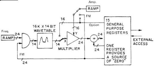
Figure 1.
The ramp and FM inputs are added together, then added to the current phase. This new phase is saved for
the next current phase and the result addresses the wavetable. The multiplier has several options to allow for filtering
and generalized arithmetic operations. The result can be stored directly in a register (by adding in the "zero" register),
or summed with another register.
III. The First Problem
When we first began working with the 4B, the only means of producing a sound was to write a program in LSI-11
assembly language setting the appropriate control bits and specifying the appropriate data for the ramp values. Having
written such a program and loaded it into the machine, there were only two ways to change oscillator connections or
ramp value data which was not taken from real time inputs : either modify and recompile the original program or
use an on-line debugging program to change bits one by one in order to hear the effects in real time. With the latter
technique one becomes quickly aware of the fact that once a ramp is enabled, it proceeds immediately on its course to
the given final value. If you want to enable two ramps at the same time, you are out of luck using this method.
IV. Syntax for Oscillator Connections
The next problem was to design a syntax for specifying oscillator connections to the 4B in a form that would be
relatively easy for musicians without extensive computer experience to comprehend and use. At this point we made
what I think is one of the most important decisions in the language design : to have the SYN4B language
address the 4B at the lowest level possible. To do this, it was necessary to assume that anyone using the machine will
have to understand the structure of the oscillators, as represented above in section II. Then it is just a matter of finding
a simple format to accomodate data for the switches and input for the FM and OPTION registers and input and output
for the adder. Our solution to this problem was as follows :
*OSC# Rn = [Rm + ] (FMx, FreqRamp, OPy or WavTabl, AmpRamp or FMx or OPy)
Given the previous explanation of how each oscillator is structured, this format for oscillator definitions should appear
straightforward and not overly complex. The only feature which might not be obvious is the use of variables to identify
the ramps for frequency and amplitude. This was done with the expectation that at some point it might be desirable to
associate various functions with any particular ramp, perhaps in a score format for playing the 4B from a note list. This
will be discussed further in section VI below.
Rn
output register for osc#
Rm
adder input register (optional)
FMx
register number from which FM input is taken
OPy
register number from which OPTION input is taken
FreqRamp and AmpRamp
variable names identifying frequency and amplitude ramps associated with osc#
Within the parentheses,
Each position is given a default value, so that the use of the oscillator connection statement is made quite simple. For example, to specify that oscillator 1 is to have R0 as the FM register (i.e., no frequency modulation), that the ramps are to be connected to the two poles of the multiplier, that R0 is to be input to the adder, and that the oscillator output is to go to R15, the user simply types :
oscl R15 = (,,,)This format is really nothing more than putting the commands for the 4B's oscillator control words into a simple mnemonic form. This is important, however, because it means that the user of the SYN4B language is actually communicating with the synthesizer on the same level as he would if he were using LSI-11 assembly language. This means that the language will not limit the user's access to the machine at all. To complete this kind of basic low level access, we also defined simple mnemonics for the ramp control words :
<code><osc#><new value>In the process of actually playing the synthesizer these commands are awkward, to say the least. Generally, when the user finds himself using these particular commands extensively to control the ramps, it becomes apparent that another, higher level command is necessary. For example, if one wishes to have a constant value of 2000000 in the amplitude ramp for oscillator 1, using this notation you would need to type :
where : <code>
IF or IA (initial value freq/amp)
FF or FA (final value freq/amp)
(symbole) DF or DA (increment freq/amp)
<new value> <new value>
real time input specifications (see section VII for details)
IA1 2000000Instead it is possible to just type :
FA1 2000000
DAI MAX (full 23 -bits as increment)
FAI 2000000 (see part V below for explanation)which sets the same bits as the three preceding lines of code. However, this ability to actually set the ramp control words directly from the high level control language means that other future users will not be limited by our present vision of how the machine can be used, or by simplified statements in which the user cannot really see what is going into the machine. I also believe that the best way to learn what each of the possible controls for the machine can do is to use the lowest level of the language when first using the machine. This helps take the mystery out of the higher-level command formats, which are used more frequently in actual practice, particularly in the case of ramp controls.
Some of these features have already been implemented in the SYN4B language, some are in the process of being implemented, and some are still in the planning stage. The simplest feature to implement was the command for setting a constant ramp value, which has the format :
PIn <value> (for frequency ramp #n)As mentioned in section IV above, these commands simply allow the user to substitute one line of code for the three lines necessary at the language's lowest level. This may seem like a very minor improvement, but with the possibility of 64 oscillators we have found that this feature has both cut down the time necessary for entering an instrument definition and made our input files more easily comprehensible.
PAn <value> (for amplitude ramp #n)
For the design and use of breakpoint functions we have used the following basic format :
FUN BP <name>This format specifies the breakpoints on a grid of 100 by 100. The first value of the x- axis is automatically set at 0, and the function is considered complete when the x value reaches 100. SYN4B then automatically sets the proper increment and final values for each ramp segment, as well as setting the interrupt enable control bits and sending the new values to the proper ramp each time an interrupt is generated by the arrival at the final value of the current ramp segment.
Y0 x1 y1 x2 y2 - - - - - - 100 yn
In order for such a function to have any real meaning for the synthesizer it must be scaled on both the x- and y- axes. The need for this scaling is important to understand. Since we may safely assume that a breakpoint function will be used to control either an amplitude or a frequency ramp, we may consider that the y- axis will represent either frequency or amplitude, and the x- axis will represent time. Now, our first question must be : what amount of time is to be represented by the 100 points along the x- axis ? The second question is : how do we know that that amount of time has passed ? It is important to realize, in this regard, that the computer has no way of knowing what time it is unless you tell it. Therefore, there must be some sort of timing mechanism built into the program which will allow us to measure time. This measurement must be made in terms of some basic unit of time, and only then may we consider that the 100 points along the x- axis of our function have any meaning at all, in terms of some number of time units. Furthermore, unless all notes or events to be controlled by the function are to be of the same duration, its length (i.e., the x- axis) must be adjustable in terms of time units. In other words, it must be scaled.
On the y- axis the situation is different but equally significant. Let us assume that the values on this scale will be used as data for ramp final values. What is the range of these values inside the 4B ? Not 0 to 100, but 0 to 2 23 -1, or 8,388,607. This is so because the value is actually represented by a 24 bit binary word, with the left-most bit saved to indicate the sign (positive or negative). Obviously, a value of 100 on a scale of 0 to eight million is not very significant. And things would not be improved by automatically scaling the function such that the maximum value of the function is 8,388,607 because this number is used to represent the maximum amplitude of the entire synthesizer. This means that the maximum amplitude for each oscillator must depend upon the number of oscillators being used for audio output. Therefore, again, it must be scaled by the user.
Scaling in time, as noted above, is dependent upon establishing some sort of time unit. We have implemented a method by which the user defines his own time units, employing an oscillator for this purpose. This will be explained in more detail in the following section on Scores. One feature of scaling in time, however, should be discussed here. Assuming that the total duration of a breakpoint function is to be variable and user specified for different notes or events, we may wish to have a portion of the function which will be non-varying regardless of the overall duration of the function. For example, if we use a breakpoint function to define an amplitude envelope, it may be desirable to set specific times for the attack and decay, leaving only the central portion of the envelope to be scaled according to the duration of the note. We have built this feature into the breakpoint function definitions by expanding the format as follows :
FUN BP <name>where <att> and <dec> are the attack and decay times in milliseconds, and the asterisks following any number of x- and y- coordinates indicate that those ramp segments are to be considered as part of the "steady state" portion of the function. This means that the ramp segments which appear before the steady state segments are calculated to have the exact duration specified in <att>, and the ramp segments following the steady state segments are calculated to have the duration specified in <dec>, leaving only the steady state portion of the function to be scaled in time.
<att>, <dec>
y0 x1 y1 x2 y2* - -* - -* - - 100 yn
Scaling the functions on the i- axis presents a somewhat different problem. Assuming again that breakpoint functions will be used in part to describe amplitude envelopes, it will be necessary to multiply these functions by one or several scaling values. This can be done to a limited extent in the 4B itself, using the oscillators as multipliers by connecting the OPTION register to bypass the wave-table. If, however, we wish to scale by several factors at once, it becomes necessary to use many oscillators as multipliers, which considerably diminishes the power of the synthesizer. A further problem with this method of using the synthesizer to do arithmetic is that there are no direct inputs to the general purpose registers (see section II). This means that there is no straightforward way to put a constant value into one of the general purpose registers so that it can be accessed by the option register for the x-input of an oscillator to be multiplied by a value in the amplitude ramp. In order to put a given value in the general purpose register so that it can be used for a hardware multiplication it is necessary to set the frequency of an oscillator to 0, set the phase of that oscillator to 900 (assuming that there is a sine wave in the wave-table, which has a value of 1 at 90°), and then put the value you wish to get out into the amplitude ramp. This method works, but is quite awkward and tends to consume too many oscillators to do simple arithmetic.
The other obvious solution to scaling is to do it all in the software, using a series of subroutines which would allow us to do various kinds of arithmetic operations on single values as well as on breakpoint functions. Here we found a fatal flaw : specifically, the LSI-11/03 which we are using, to control the 4B is simply not fast enough to do very many multiplies in real time while servicing interrupts generated by ramps and real time input devices.
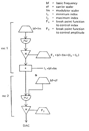
To illustrate this problem, let us define a simple, single modulator FM instrument using the 4B hardware for all the multiplications. We will assume that the ratio of carrier to modulating frequency is to be constant, and therefore the carrier will be expressed as <basic frequency>*<carrier scaler>, and the modulating frequency will be expressed as <basic frequency>*<fm scaler>, with the convention that scalers will be constant. If it were possible to use the software for arithmetic, our instrument could be represented as in Figure 2. The use of the various scaling factors is quite important if we wish to have precise control over timbre. With software arithmetic, as shown in Figure 2, we need only two oscillators to define this instrument, which means that we could have up to 32 such instruments playing at once. If, however, we are forced to use the synthesizer hardware for our multiplications (assuming we can do the subtraction I2 - I1 by hand), and including the need to set the frequency to 0 and the phase to 90° in order to put an initial constant value into the general purpose registers, we end up with the instrument in Figure 3. In this diagram I have included only those parts of each oscillator which are used, in order to simplify the schematic representation. It should be clear, however, that instead of using two oscillators, we now must use eight. This means that we may only have a maximum of eight such instruments at once. In effect, we have had to diminish the capacity of the machine by a factor of four in order to do our scaling operations.
The need for scaling breakpoint functions, and the problems involved in doing that scaling through the 4B hardware should now be clear. Given the 4B synthesizer and the LSI-11/03 which we have to work with, there seems to be no ideal solution for this problem, or for the more general problem of doing arithmetic operations in real time via software for the LSI, short of having a high speed arithmetic unit designed, built, and mounted on the LSI. Therefore, we have made a series of compromises concerning both the scaling of the breakpoint functions along their y- axis and the use of arithmetic equations.
For the breakpoint functions, we have implemented a set of fixed scaling possibilities, thus expanding our format for the functions to the following :
FUN BP <name> a,b,cwhere a and b are additive and multiplicative factors, respectively, and c is a shift factor. This means that the value of each breakpoint is evaluated by the equation
<att>, <dec>
y0 x1 y1 x2 y2* - -* - -* - - 100 yn
value(n) : = (a + b * y(n))*2cThat is, each y- value of the function is multiplied by b, offset by a, and then the binary representation of that number is shifted c bits to the left (with a shift to the right if c is negative).
For the evaluation of more general arithmetic equations, we have made use of the previously described "hardware multiply" within the 4B, and also, to a more limited extent, devised a method for evaluating expressions in which all components of the expression are read from the real time inputs, which will be discussed in more detail in section VII.
To return to the five features which I mentioned at the beginning of this section (multiple ramps, scaling of functions, use of durations rather than increments, evaluation of arithmetic expressions, and constant ramp values), it will be clear that all five have been implemented to some extent, but often with a certain amount of compromise. This makes for a language which, at this time, is in some ways more awkward to use than I would like. However, the awkwardness is primarily a function of the limitations of the machines, and we have had to decide very often between being able to do something awkwardly or not at all. And in order to give users of the system the greatest possible flexibility, we have always opted to include features which might be a little cumbersome to use, but allow for more complete control over the synthesizer.
Figure 2.
In this diagram, the trapezoid represents an input, generally equivalent to the frequency or amplitude ramp in Figure 1. The half-circle represents phase accumulation and lookup, and the triangle stands for the multiplication. The rectangle represents the addition before storage in a general register. Here, it is assumed that the input coefficients are calculated by the LSI-11.
Figure 3.
Figure 3. An expansion of Figure 2 which performs coefficient calculation in the hardware.
The basic questions which we had to answer in our planning were : 1) If we are to have a score, then we must have some way of specifying durations flow is this to be done, since there are no timers built into the synthesizer, 2) What is the most easily comprehensible and at the same time most flexible format to use for notating a score ? 3) Should a score be monophonic or polyphonic ? That is, do we want to specify events one voice at a time ? 4) Should the score be completely separate from the instrument definitions, as it is in non-real time languages such as MUSIC V or MUSIC 10 (1), or should it be possible to mix note list and instrument definition ? 5) Should input from the score be used entirely separately from control by real time inputs ? If not, how can the two methods of playing be used together ?
First is the problem of specifying durations. This is done by using one or more oscillators as timers. To do this, the software needs to set a ramp with specific initial, increment, and final values to yield a user specified duration for a basic unit of time. The user then expresses durations in his score in relation to this basic unit. The format for defining a timer is :
TIMn <duration>where n is the oscillator number used for the timer, and the duration is either expressed in milliseconds or as a real time input specification. When expressing durations in the score, the symbol D is used to express the basic unit given to the timer. Other durations are then expressed as arithmetic expressions relative to this basic unit. For example, if we have set the basic unit for the timer to be 100msec (.1 seconds), then D*2 would indicate a duration of .2 seconds, and D/2 would indicate a duration of .05 seconds. It should be noted here that the problem of evaluating arithmetic expressions in the score need not present any problem for the LSI-11 with its relatively long multiply time, as long as the score is not to be interpreted in real time.
The problem of finding the appropriate format for the score has not yet been satisfactorily solved, but it may be interesting to examine the two possibilities which we have considered. The first possibility is to use a fixed parameter field format, similar to that used for MUSIC10 note lists. In this case, the system would demand that a certain number of fields in the list for each note or event be used to express required data, such as duration, instrument name or number, begin time, etc. The remaining fields would then be associated with ramps, which would be specified in the oscillator definition as Pn. That is, if we define oscillator 1 as follows :
OSC1 R15 = (,P3,,P4)then we will know that the values or functions to be put into the frequency and amplitude ramps for oscillator 1 will be found in the third and fourth fields of data for each note. Assuming that OSC1 is defined as instrument 1, and that fields 1 and 2 are reserved for instrument number and duration, respectively, a line of score in this format might look like this :
1 D/7 200 40000000One disanvdatage of this system is that it is possible to imagine values which one would wish to specify in the score, but which may not be used directly in an oscillator connection statement. For this reason, it may be more desirable to ask the user to specify at the beginning of each score the definition of each field. For example, we may wish to have the same oscillator connection as above, but use breakpoint functions for both ramps, scaling the functions differently for each note. We might then begin by setting breakpoint functions called FRQ1 and AMP1, then define two new breakpoint functions as :
FUN BP P3=FRQ*FSCALA line of our score input would then look like this, with instrument number indicated in the first line :
FUN BP P4=AMP1*ASCAL
To even further extend this possibility, we might assume that indeed we could use different breakpoint functions for different notes. In this case we might assign FRQ1 and AMP1 as variable names, and call on predefined breakpoint functions which we will call F1 through F4. Two lines of score input would then look like this :
SCORE INS1 (DUR FSCAL ASCAL) D/7 10 4000
The advantage to this method is that it allows for considerably more flexibility than a fixed field method. The disadvantage is that it may prove to be slightly more cumbersome to use, since the format for each score must be set up individually.
SCORE INS1 (DUR FRQ1 FSCAL AMP1 ASCAL) D/7 F1 10 F3 4000 D/2 F2 20 F4 5000
The next question in designing the score format for the 4B is whether we want to use polyphonic or monophonic scores. In a rnonophonic score, such as the examples above, we must indicate that a block of score data is to be applied to a specific instrument. Each event for that voice is then listed in chronological order. One can of course play several instruments at the same time using this method, but the score for each instrument must be entered separately. In a polyphonic score, on the other hand, each note for each instrument played must be listed in chronological order. This method, which is used in MUSIC V and MUSIC10, requires an instrument name and a begin time for each note. In my opinion, the monophonic method appears preferable, again because it allows the user considerably more flexibility, in that several instruments may be played independently at the same time. In real time performance, which is one of the unique capabilities of the 4B synthesizer, this flexibility might be employed by starting scores for various instruments at different times, to be decided at performance time. Similarly, it would be possible to use different timers for different instruments, and to control these timers from real time inputs. In this way the tempi of different musical lines could be varied independently and in real time. The only advantage of having a polyphonic score format is that the specifications for chords and for tightly controlled counterpoint may be somewhat simpler for the user, but I believe that this is counterbalanced by the loss of flexibility and the general awkwardness of this approach for non-chordal musical textures. The ideal solution for this particular problem may be, in fact, to have both systems of score notation available to the user, although this has not yet been implemented in SYN4B.
The last two questions to be considered in the design of a score format have to do with how the score portion of the control language relates to other portions of the language, and the solutions to these problems depend to a large extent on consideration of the real time performance nature of the 4B machine itself. The questions are 1) should the note list coexist with or be separate from the instrument definitions, and 2) should control from a score coexist with or be separate from control by real time inputs. The answer is that the score should coexist with both instrument definitions and real time inputs.
To consider the first of these problems it helps to have some familiarity with the structure of music programs for larger, non-real time computer music systems, such as MUSIC V or MUSIC 10. In these programs the user begins by defining instruments and functions. As soon as a note list is begun, the program will accept no more instrument or function definitions because it begins calculating a sound file for storage on disk. This is all quite reasonable, considering that these programs calculate music files rather than send information to a synthesizer. The 4B, however, has entirely different needs. Since the synthesizer is, in effect, always capable of producing sound with whatever oscillator connections and ramp data it has, there is no particular reason to separate the score from the instrument definitions. On the contrary, the potential of intermixing the two presents very interesting possibilities. For example, there is no reason why one could not have one set of instrument definitions, followed by scores for those instruments, followed by some modifications of the instruments, followed by more scores. In this way, very different sounds could be generated from the synthesizer at different times within the same performance without having to enter any new input files for the SYN4B program.
This mode of operation might be even more interesting if, for example, we included the possibility of triggering the beginning of a score from a real time input. This brings us to the final question in the design of the score portion of the program, namely, whether or not one should be able to combine the score with real time inputs. The use of a real time input as a switch to trigger the beginning of a score is only one of the possibilities to consider in this combined score/real time mode of operation. Another possibility might be to trigger each event in a note list by pressing a key on the keyboard. This would mean that the note itself would be dependent upon the keyboard for nothing but its initialization, with all its other aspects controlled in the score. Another possibility would be to have the timer for a particular instrument controlled by a real time input device, so that, while the notes and relative durations are fixed in the score, the tempo could be varied over a wide range in performance. Also of great interest might be the ability to notate certain parameters of an instrument in a score, while controlling other parameters from the real time control devices.
As should be obvious, the combination of real time input with preset note list data would appear to be one way in which the nature of the 4B as a digital synthesizer might be most fully exploited. One has the possibility of great exactitude and tightly controlled complexity which is almost impossible to achieve with an analog synthesizer, while having the potential for real time user interaction with the machine in performance, which is generally not possible with computer generated sound.
Because of this wish to take advantage of the potential for interacting with the score in real time, the actual code for creating the score portion of the program has become very much intertwined with the processing of the real time input devices, particularly on the level of program interrupts generated by the real time devices as well as by the ramps. While a technical description of the inner workings of this part of the program is beyond the scope of this paper, it may be of interest to mention the general approach we have taken to processing the several levels of program interrupts generated by actually playing the synthesizer in this way, which could easily overtax the LSI-11/03, which is a relatively slow computer. This has been done by implementing a "waiting loop", which is in operation whenever the synthesizer is not taking data from the teletype. It is within this waiting loop that the SYN4B program processes data from the real time input devices, keeps track of program interrupts, and determines when the next note or event is to be initialized.
One last idea which came out of the planning for the note list format should also be mentioned here, and that is the
inclusion of a limited amount of decision making capability for the program itself, in the form of if - then, goto
and wait commands, with the decisions determined by the state of one of the real time inputs. When used in the note list, this
could allow the user, for example, the option of looping through one section of a score until a certain button is pressed,
at which point the program could proceed through the rest of the note list, or be directed to an entirely different part of
the score, or even be directed to a block of code which changed the oscillator connections and then sent the program
back to another block of score input. This, I believe, provides a truly idiomatic use of the synthesizer by allowing the
performer to make formal decisions about the music in performance without sacrificing the kind of tight control of detail
which is available through the use of a score.
The first basic decision which we made concerning the use of the real time inputs was that ideally we would like to be
able to use them anywhere in the program : to specify values for ramps, to define breakpoint functions, and as
inputs for arithmetic expressions, as well as for logic in the if - then statements described in the previous section. It
also is essential, particularly in the case of the keyboards, that the real time inputs be able to trigger events, which
means indicating to the waiting loop that the various ramps for a particular instrument are to be initialized.
The process for reading data directly from the real time inputs into a ramp value is fairly straightforward. The only
problem to be dealt with is the fact that, except for the keyboards, the data is all in either 8 bit or 16 bit format, whereas
the 4B uses 23 bits for all ramp data. This means that if the value of a slide pot, for example, is put directly into the final
value of an amplitude ramp, it will be 215 (32678) times smaller than the maximum amplitude : which means that it will be
inaudible. The problem, then, is to find a simple means to scale the values read from the pots. We have implemented
several different methods of doing this.
The first method is to concatenate three 8 bit pots into one 24 bit word. This is done with the following format :
VII. Real Time Inputs
I have been referring to the real time input devices throughout the previous section without being very explicit about
what those devices are. In fact, we have been working with a box of real time controls built by David Cockerell at
IRCAM, for use with the 4B synthesizer. This box includes a total of 48 slide potentiometers in two banks of 16 and 32
each, a two directional joystick, and one foot pedal, each of which yields 8 bits of binary data. In addition there are two
rows of buttons which may be read in a number of ways : depressed or not, on or off (indicated by lights within the
buttons); plus, one row of buttons may be read as a 16 bit word, while the other may be used to access sixteen virtual
values of 16 bits each of which are set by means of a spinwheel. Finally, there are two keyboards, one of which is a 61
key organ keyboard, and the other of which is an 8 by 9 button matrix ; any note or button on either keyboard is used to
refer to a specific location in a user-definable table in the LSI-I I memory. We have used the following general format to
identify real time input devices :
<device type>(<number>)
where the <device type> may be either a single input or several which are grouped together, and the number indicates
the specific member of the group. Some of the mnemonics for real time devices which have been implemented at this
time include :
PBA(n)
E pot #n of the first bank of slide pots
This list, however, should not be seen as definitive. It will be possible for a user to define his own device name, in
which he may include any of the specific real time inputs desired, so that any number of inputs which are used to put
together parameters for a particular sound may be grouped as a single real time input device.
PBB(n)
pot #n of the second bank of slide pots
PED
pedal
KBD(n)
keyboard 1 or 2
STV
joystick, vertical scale
STH
joystick, horizontal scale
SPW(n)
virtual spinwheel #n, selected from lower buttons
<code><osc#><origin>(x,y)
where <code> represents the symbolic name of the destination within the 4B (such as PI1 for constant frequency of
oscillator 1), <origin> is either PBA or PBB, and x and y indicate the first and last of no more than three pots to be
concatenated. Using this format, we may indicate a constant value for the frequency of oscillator number one, to be
determined by the concatenation of the first three pots in pot bank A, with the following statement :
PI1 PBA (1,3)
While this was useful in the first stages of testing the machine and the SYN4B program, it became
obvious that it would be quite inconvenient to operate the controls in this manner at all times. The obvious solution to
the problem was to use some form of scaling so that a full 23 bits of information could be taken from an 8 bit pot. To
do this we incorporated the scaling feature which we used in our breakpoint functions (see section III) into the
symbolic names for the real time inputs, as follows :
<code><osc#><origin> a, b, cwhere a, b, and c represent additive, multiplicative, and shift factors (as explained above). Thus, to take a full range of values on 23 bits from an eight bit pot, we need to multiply the value in the pot by about 30000, with the statement :
PAI PBA(1) ,30000,which indicates that the pot is to have an additive factor of 0, a multiplicative factor of 30000, and a shift factor of 0. Once one becomes accustomed to this method of scaling the output of the real time inputs, it becomes quite simple to scale the values to have virtually any range desired. Furthermore, by using a combination of the scalers and the concatenation feature, it is possible to use the pots for a combination of wide range selection and fine tuning of values. For example, the following statement would assign the first pot of pot bank A to control the frequency of the first oscillator, while allowing fine tuning with the second pot of the same pot bank :
PI1 PBA(1,2) ,,7Having in this way adopted the symbolic representation of the real time inputs to tire format of the breakpoint functions, we have also expanded the concept of these functions to include the possibility of a type of function defined simply by points. This 'point function' simply returns the value of a given input, scaled with the same format as above. However, if a series of pots is listed, the function will return the value of the first pot the first time it is called, the second pot the second time it is called, the third pot the third time, etc. When the last pot has been read, the function returns to the beginning of the cycle. The format for this type of function is :
FUN PT <name><origin>(x,y) a,b,cwhere a, b, and c are scale factors, as above,
FUN PT SEQ PBB(1,32) ,4000,This function might then be used as the frequency control for an oscillator with the statement :
PI1 SEQWe have also implemented the ability to define breakpoint functions with the real time inputs, with a statement such as :
FUN BP f1 PBA(1, 8)in which breakpoints are set at 8 equally spaced points on the x- axis, and the y- value of each breakpoint is read from pots 1-8 in pot bank A.
Although, as mentioned in section V, we have not yet implemented the use of arithmetic expressions to be evaluated in
real time with the SYN4B language because of the speed limitations of the LSI-11, the ease of access to the values
contained in the real time inputs has allowed us to implement this feature on a limited scale, with the stipulation that all
components of an arithmetic expression must be read from the real time inputs. This is another feature of the
language which is more cumbersome than I would like it to be, but is certainly an improvement over the limitation of
being able to do arithmetic only in the 4B itself. Or in the scalers used with real time input assignment statements and
function definition statements. With this feature, for example, it is possible to construct an FM instrument in which the
ratio of carrier to modulating frequency and the range of modulation indices are set by values in 4 of the virtual spin
wheels, while the basic frequency of each note is determined by the keyboard or by a score.
Many of the problems which we encountered in the design of SYN4B can be instructive in the realm of hardware
design for digital synthesizers. For example, the problems of scaling and the waste of oscillators for use in evaluating
arithmetic expressions may be avoided altogether by separating the components of the oscillators so that adders and
multipliers may be accessed independently. Similarly, the synthesizer may be constructed so as to include a number of
timers so that oscillators would not have to be sacrificed for this purpose as well. These improvements, as well as
many others which stem from the experience of using the 4B, have in fact been incorporated into the design of di
Giugno's newest synthesizer, the 4C.
While our solutions to the particular problems we encountered may help others solve similar problems, I believe that
those who are simply users of computer music systems, and who will never be faced with the specific problems
discussed in this paper, can benefit from having followed our progress. If one is to write "idioniatic" music for or with a
computer, it is essential to have some understanding of why and how your instrument (i.e., the computer) works. This
may be seen as analogous to the way in which most instrurnentalists who utilize new performing techniques find it
essential to understand the physical and mechanical means by which their instrument produces sound. If the computer
music cornposer makes a similar effort to understand why his software works the way it does, at the very least he may
be led to write in a way that fits the machine idiomatically. Furthermore, if the composer can understand a particularly
troublesome feature as the result of a decision concerning a specific problem in the design of his system, he may be
able to find another solution which is more suited to his needs.
____________________________ ____________________________VIII. Final Thoughts
We have followed the development of the major features of the SYN4B language. In general each feature has been
approached with a certain ideal form of implementation in mind, and very often that ideal had to be compromised to
some extent by the limitations of the machines which we were working with. To a greater or lesser extent this must be
true of all computer music systems.
Acknowledgements
The work documented in this paper was made possible only by the cooperation of a large number of people who gave
very freely of their time and ideas. Much of the fornal structure of the language took shape under the influence of
Max V. Mathews, James R. Lawson, and Bruce F. Leibig. Virtually all of the coding of the language was done by
Philippe Prevot. I would also like to thank Andy Moorer for his careful reading of this paper and his many helpful
suggestions, and finally, Pepino di Giugno for his patience in guiding Philippe and myself through the inner workings
of his synthesizer.
Note
Server © IRCAM-CGP, 1996-2008 - file updated on .
Serveur © IRCAM-CGP, 1996-2008 - document mis à jour le .