
Tous droits réservés pour tous pays. All rights reserved.
| Serveur © IRCAM - CENTRE POMPIDOU 1996-2005. Tous droits réservés pour tous pays. All rights reserved. |
A bandpass analog filter, whose parameters are all under computer control was built at IRCAM. This filter allows real-time signal processing of sounds. A microcomputer controls the different parameters of the filter. The program of the microcomputer and the functions of variation of the filter are fixed by a PDP-11 computer.
The block diagram of the instrument is described in fig.1. The instrument was conceived as a stand-alone instrument. This is why a microcomputer was used. The 8085 was chosen because of the great variety of its peripherals and its compactness.
But in order to profit of all the advantages of the PDP-11, the 8085 was interfaced to the PDP-11 through the UNIBUS. The 4K memory of the 8085 is considered by the PDP-11 as its own memory -- (although only the 256 first bytes can be addressed directly by the PDP-11). This allows maximum flexibility in developing the system, and the final program of the 8085 is stored in the disk of the PDP-11.
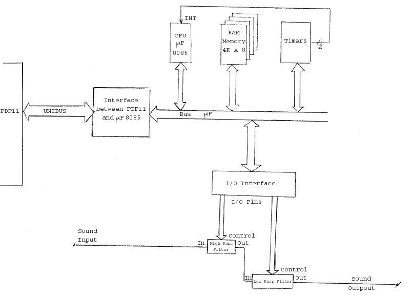
Figure 1. Block diagram
The 8085 considers the filers as output peripherals. The elements that compose the  P are :
The program of the 8085 and the functions of variation of the filters are stored in the 4K memory. The 8253 contains 3
programmable timers that are used to interrupt the P, to allow a change of the frequency of the filters, as described in fig. 2.
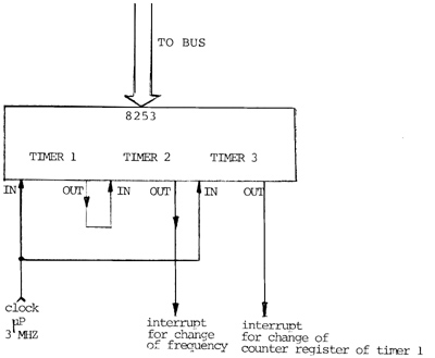
Figure 2. Timer section
The frequency of variation of the cut-off frequency of the filter is fixed by the output of timer 2. As it is shown in fig. 2 the input of timer 2 is the output of timer 1. This allows the possibility of modulating the frequency of timer 2 by a function loaded in timer 1. The frequency of the output of timer 2 is proportional to :
COUNTER REGISTER 1 X COUNTER REGISTER 2
Timer 3 controls the rate of change of the function loaded in timer 1. We achieve in that way a Frequency modulation process, which allows us to change the rate of variation of the filter's frequencies.
We wanted to realize a bandpass filter with sharp slopes but with programmable low and high frequencies.
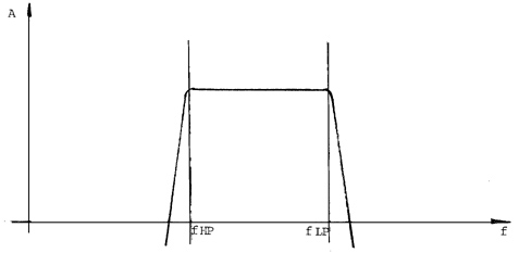
Figure 3. General shape
A combination of a high-pass filter in cascade with a low-pass filter gives a bandpass filter. If we change the cut-off frequency of the LP and the HP filters we achieve what we wanted to realize. The configuration chosen for the filter was the state variable configuration as described in fig. 4.
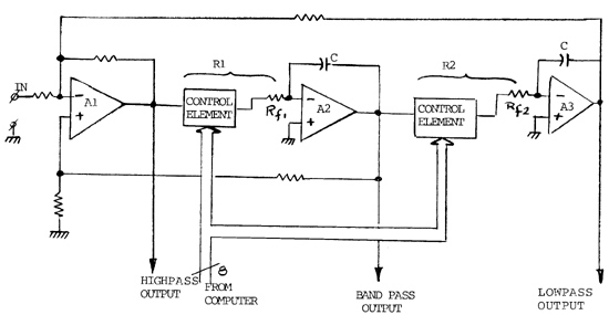
Figure 4. Basic filter
Each filter is a Legendre Filter of order 6. This type of filter was chosen because it gave a maximum slope with minimum ripple in the pass-band for a given order.
So each filter is composed of 3 stages as described in fig. 4. With that configuration we achieved 50 dB/octave attenuation. The control element of the filter is an attenuator that fixes the cut-off frequency of the filter as it combines with Rf1 and Rf2.
We achieve so a variable resistor R1 and R2. In that configuration the frequency of the filter changes but the quality factor Q remains constant.
A companding multiplying DAC (DAC 76) was chosen as the control element. The main advantages of that DAC are :
The main disadvantage of that DAC is that the analog input accepts only unipolar voltages. It is necessary to substract the output of the DAC with the output of another DAC in order to restore a bipolar signal as described in fig. 5.
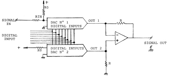
Figure 5. Control element
Since two different DAC's give slighty different outputs for the same digital input, the difference of the DC component is never zero, and we hear a "click" when the frequency is changed. That click was removed by the following circuit (general diagram).
Figure 5. Anti-click circuit
Since the "click" occurs when the frequency changes i.e when the interrupt is active, if we sample the signal at a constant rate and hold it when the interrupt is active, we get rid off the clicks. In pratice it was not possible to remove the whole part of the clicks because they lasted longer than the time of the interrupt and they are also dependant of the frequency and the Q of the filter ; but the output signal is not disturbed by those "clicks" because they remain at a very low level.
The bus of the PDP-11 is an asynchronous bus. This property allows easy interface between the PDP-11 and the
microcomputer. The memory of the P is considered by the PDP as its own memory and the memory is addressed
when the P is in the DMA mode. This allows very quick communication between the PDP-11 and the P.
Only the first 256 bits are addressed directly, the others are adressed indirectly through a control register. The general diagram is shown in fig. 7
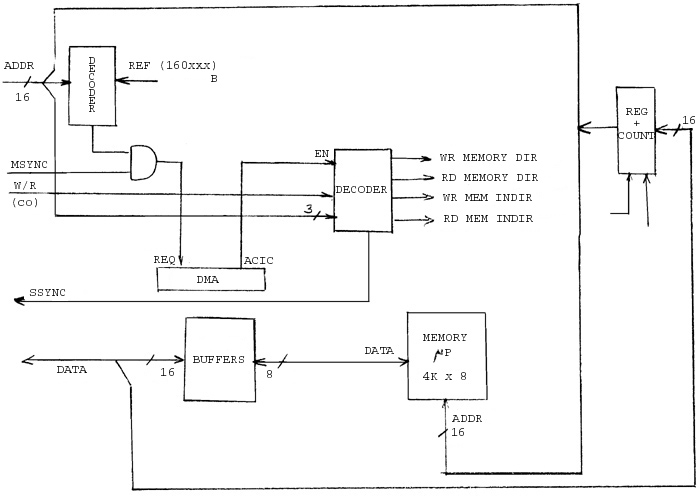
Figure 7. Interface block diagram
When the PDP wants to write or read into the P's memory, it sends an address starting with 160XXX8. That address
is decoded and the P enters the DMA state.
The instruction is then decoded and the data are written or read. A SSYNC signal is sent
back to the PDP-11, announcing the end of the instruction. The 256 first bytes are addressed
that way. If the PDP-11 wants to address the remaining of the 4K bytes, it first writes the address it wants to go to, in a
register + counter and then writes (or reads) the content of the memory addressed by the register. At the end of the
instruction the counter is automatically incremented. It is possible to read/write to any memory location by only one
instruction, using the address of the memory as the output of the register. That method allows us to communicate with
the 4K x 8 memory of the P, and using only 260 words of the PDP-11.
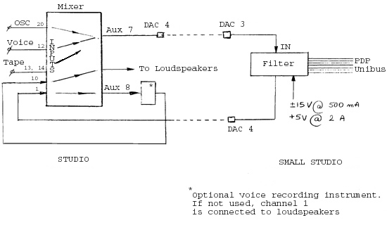
Figure 8. Connection diagram
That diagram describes the connections with the facilities of the 4C cables (supposing the 4C machine is not working at the same time).
A few programs were developed in order to run the filter instrument. These programs exist on the disk of the PDP.
This program loads the instructions to the 8085. These instructions are written with the mnemonics developped by Prolog. A program called PROLOG.MAC converts all the instructions in their octal equivalents.
This program holds the microcomputers which enters the DMA state.
This program resets the microcomputer.
This program sets any function either by segments or their harmonics.
This program displays any function on the CRT.
This program loads a given function (defined by WRFUN) into the P. That function defines the variation of the
Low-pass filter.
The same as LDFIL but applies to the high pass filter.
The same as LDFIC but applies to the modulation function (timer 1 of the 8253).
This program sets the rate of change of the filter.
The same as FREQLP but applies to the modulator frequency.
That program is a combination of all former programs and allows a complete working of the filter.
The filter prototype described here allows us the maximum performance for signal processing by filtering, in combining the simplicity of analog filters with the accuracy of digital control. The definite instrument would be a stand-alone microcomputer (with non volatile ROM's instead of RAM's) and a bank of filters all of them digitally controllable. Another feature that will be introduced will be the possibility of synchronization between the input and the variation of the filter, for example the attack of an instrument will trigger the function, or a definite frequency will trigger the function.
____________________________
Server © IRCAM-CGP, 1996-2008 - file updated on .
____________________________
Serveur © IRCAM-CGP, 1996-2008 - document mis à jour le .